Revit for Precast Concrete: Essential Techniques for Modeling and Documentation

Precast concrete modeling and documentation in Revit enhance project efficiency by utilizing accurate 3D representations, clash detection, and in-depth scheduling. This approach streamlines coordination, mitigates errors, automates drawings, and ensures precise fabrication data for improved collaboration and efficient construction.
Business Need for Precast Concrete Modeling and Revit Precast Documentation
In the construction industry, the demand for accuracy, efficiency, and rapid project delivery has increased significantly, especially for complex structures. Precast concrete, renowned for its durability and ability to reduce construction timelines, plays a crucial role in meeting these demands. However, maximizing the benefits of precast concrete necessitates accurate and detailed modeling and documentation processes.
Revit, a leading Building Information Modeling (BIM) platform, offers a robust solution for managing precast concrete projects from design and manufacturing to installation. The ability to model precast elements within a 3D environment, integrate them with other project elements, and generate accurate documentation is essential for delivering projects on time and within budget.
Challenges with Precast Concrete Modeling and Documentation without Revit BIM
Without Revit BIM, precast concrete modeling and documentation encounter various challenges, including issues with manual drafting, visualization difficulties, and inefficient coordination among project teams. Limited data integration hinders precise fabrication, while inconsistencies in document management can lead to miscommunication, rework, and delays during construction and installation.
Top techniques to create, detail, and document precast concrete in BIM with Revit
Dividing Revit Walls into Precast Panels
In Revit, dividing walls into precast panels involves using the “Split Element” tool to create individual segments along the wall. Users can define the panel location and size to ensure accurate alignment with structural requirements. Each panel is assigned unique properties, fabrication details, and materials, enabling effective coordination and documentation. This approach enhances accuracy and streamlines the precast production process.
Designing and Laying Out Precast Slabs in Revit
Precast concrete modeling and documentation for precast slabs involve precise 3D modeling using specialized software. Engineers can define reinforcement details, dimensions, and connection points to ensure accurate geometry. Once modeled, layouts are generated, including detailed shop drawings that specify lifting points and embed placements. This process facilitates seamless fabrication, logistics, and installation while ensuring adherence to project specifications and maintaining structural integrity during assembly.
Adding Details, Connections, and Cutouts to Slabs and Precast Panels
In precast concrete modeling, incorporating details, connections, and cutouts on wall panels and slabs utilizes 3D modeling techniques. Designers can leverage software tools to define connection points, embed systems, and necessary cutouts. Employing parametric modeling allows for efficient adjustments to ensure compatibility with structural needs. This approach facilitates precise documentation, streamlining fabrication and assembly while minimizing errors during construction.
Incorporating Column Connection Details: Corbels, Column Shoes, Bolts, and More
Incorporating connection details for precast concrete columns requires accurate definition of corbels, column shoes, and bolts within the 3D model. This process involves using specific Revit families to define connections, reinforcing constraints for accurate positioning, detailing bolt placements, and embed locations. Proper documentation of these connections ensures structural integrity and promotes seamless coordination during prefabrication and installation, reducing potential on-site conflicts.
Positioning Lifting Anchors Based on Center of Gravity
In precast modeling, lifting anchors are inserted based on center of gravity points to ensure balanced lifting. Using Revit, the center of gravity (COG) for each precast element is calculated. Anchors are strategically positioned around the COG for even load distribution, ensuring safe transport and handling. These anchors are precisely placed using manual or automated parametric tools to achieve the required alignment.
Embedding Cuts, Anchoring Holes, and Connection Plates in Beams
Embedding cuts, anchoring holes, connection details, and plates into beams is achieved using parametric families in Revit. These elements are added by defining their placement, geometry, and relationships within the beam’s structure. Custom-built families for embeds, plates, and connections ensure accurate placement, while 3D views facilitate visualization. Automated documentation streamlines detailing and generates precise shop drawings for fabrication.
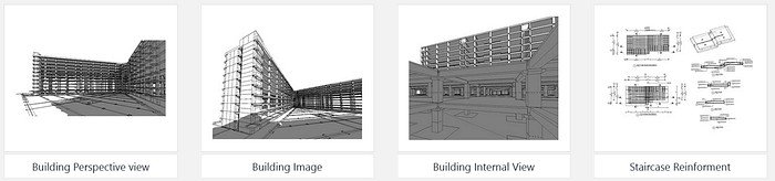
A precast contractor from the UAE approached Hitech CADD Services for a residential project. The contractor provided CAD drawings, PDFs, and Excel files. Using Revit and Navisworks, the team created and audited a 3D model at Level of Development (LOD) 450. BIM360 served as the collaboration platform for storing and accessing project files. Despite various challenges, Hitech CADD Services utilized object-based modeling, 5mm clash coordination for M60 concrete grade, and various BIM precast workflows to achieve accurate precast concrete modeling and documentation. From the 3D precast model, precast project documentation, including rebar shop drawings and bar bending schedules, was generated. The final deliverables resulted in:
• 100% accuracy of precast elements
• Cost and time savings
• Improved production quality due to precise shop drawings
• Expedited and accurate erection planning and sequencing based on unique structural element IDs.
Modifying and Updating Precast Connection Details
In Revit, updating and modifying connections for precast elements involves adjusting connection parameters, including inserts or reinforcement bars, within the 3D model. Users can define custom connection types or utilize connection families to ensure alignment with structural needs. Parametric updates ensure automated change propagation to associated elements, maintaining consistency in documentation, fabrication details, clash detection, and streamlined coordination.
Reinforcing Precast Walls in Revit
Reinforcement for walls is detailed by embedding rebar cages or meshes within the wall panels. Using Revit, reinforcement is 3D modeled, precisely placed based on load requirements, and coordinated with structural elements. This includes horizontal, vertical, and diagonal bars, as well as connection hardware. The documentation includes in-depth shop drawings, such as bar-bending schedules, for fabrication.
Reinforcing Precast Beams for Structural Integrity
Precast beam reinforcement involves the accurate placement of rebar within the beam to meet structural design requirements. In Revit, reinforcement is modeled using Rebar tools that enable accurate 3D representation. This includes defining bar shapes, sizes, and spacing to ensure proper alignment with openings and embeds. The model generates detailed fabrication drawings, schedules, and reinforcement data to improve manufacturing and enhance construction accuracy and efficiency.
Assigning Mark Values to Precast Elements Based on Custom Rules
Assigning mark values involves creating predefined rules in Revit to ensure consistent element identification. These rules generate unique marks for each precast element based on parameters such as location, geometry, and fabrication needs. This automated process simplifies element tracking, enhances coordination, and ensures accurate documentation and scheduling.
Automating Shop Drawings and Assembly Documentation with Dimensions and Schedules
Creating assemblies and shop drawings in Revit for precast concrete involves automating dimensions and scheduling through parametric modeling. Each precast element, modeled with precise geometry, is converted into assemblies. Revit’s tools automatically create detailed shop drawings by linking the 3D model to dimensioning, customized schedules, and views. This ensures accurate, fabrication-ready documentation and streamlines the production workflow.
Conclusion
Precast concrete modeling and documentation in Revit significantly enhance project efficiency by utilizing precise 3D representations, clash detection, and automated scheduling. By streamlining the coordination process, minimizing errors, and ensuring accurate fabrication data, Revit empowers project teams with seamless collaboration, shorter project timelines, and reduced costs. Furthermore, Revit’s capabilities enhance the entire lifecycle of precast concrete projects, from design and construction to ongoing maintenance, providing consistent and reliable results.
